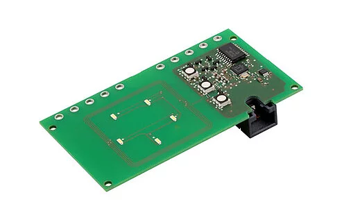
RFID/LED boards
One common authentication method is RFID (radio-frequency identification) chips. This also includes NFC (Near Field Communication) technology. These form the basis of all charging cards. Central to the identification is the so-called UID (Unique IDentifier) of an RFID chip. This is a unique code that represents the identity of a chip.
1. Hardware
Here's a list of available HMI RFID hardware modules:
1.1. Associated equipment
- Display (for visualization): DPM2X16FP Display Module
1.2. Installation and activation
The RFID module is placed beneath a semi-transparent part of the charging system housing. It should be positioned with a minimum distance of 20 mm from any metal surfaces or metal components to ensure optimal reading performance.
- As a Manufacturer
- As an Operator
- Log in to the Legacy Config UI using the Manufacturer Login Credentials
- Under Manufacturer set
Enable RFIDtoOn - Under Manufacturer, set
Type of DisplaytoBender LCD-Module DPM2x16FP - At the bottom of the Legacy Config UI, click to apply the changes
When no RFID module is installed, set Enable RFID to Off. This prevents error messages.
The Manufacturer must have set the HMI up correctly
- Log in to the Config UI using the Operator Login Credentials
- Under AUTHORIZATION > RFID Settings set
Enable RFIDtoOn - At the bottom of the Config UI, click , then click to apply the changes
2. RFID LED indications
When presenting a RFID that either has not been presented for a while or has never been presented, it might take some time for the backend to recognize the RFID. When the LEDs show that the card has been rejected, wait some time and present it again.
3. Charge Controller LED indications
- CC613
- CC612
- ICC1324
- Regular
- Eichrecht
- Ethernet indications
The status LED is to be found on the front of the controller.
- Regular
- Eichrecht
- Ethernet indications
The CC612 has three LEDs (Alarm, Ready, PLC) that are to be found on the controller.
The CC612 does not have an integrated Ethernet Port. The Ethernet activity is indicated by the USB adapter.
- Regular
- Ethernet Indications
4. RFID support
4.1. Standards
Supported RFID-related standards:
4.2. Tag types
The Charge Controller family supports all MIFARE® variants:
4.3. Additional notes
- With the MIFARE® DESFire® EV2, we support the EV2 security features
- Only the UID can be read
- Limited support for rolling UIDs. We advise against rolling UIDs
4.4. Recommendations
- For increased security, always use EV2