
Mobile generators are indispensable aids when power needs to be supplied to equipment that has no direct access to a permanent installation. This applies e.g. to building and assembly sites, rescue missions, and also to events.
Mobile generators can also supply sections of permanent installations in which the failure of the public power supply can result in critical situations, e.g. in buildings used for breeding animals, fire stations, etc. In this context, special attention must be paid to protection against electric shock, since the users are typically not very knowledgeable about electricity.
The range of application possibilities for mobile generators is often matched by the variety of discussions about the implementation of necessary protective measures against electric shock. On the one hand, this is understandable because of the many standards that generators must satisfy, and thus also various statements and assertions regarding the necessary measures.
The use of the earth spike in particular is a constant source of misunderstandings. To ensure that the protective devices work properly, the following distinctions must be made in terms of application:
The most important references for protection against electric shock are the protective measures defined in the basic safety standard DIN VDE 0100-410 (VDE 0100-410):2007-06. These measures are explained in more detail in terms of their application for mobile generators in the new DIN VDE 0100-551 (VDE 0100-551):2017-02 Annex ZC.
In practice, the following basic protective measures are used for mobile generators according to DIN VDE 0100-410 (VDE 0100-410):2007-06:
These are therefore to be considered as two completely separate protective measures which also differ considerably in their practical application.
According to DIN VDE 0100-410 (VDE 0100-410):2007-06, automatic shutdown is a protective measure in which
protective equipotential bonding via the main earthing bar and
automatic shutdown in the event of a fault.
Automatic shutdown in the event of a fault must be assured by a corresponding protective device with isolating properties (e.g. circuit breaker and residual current device RCD). In order to ensure the necessary protective earthing / protective equipotential bonding according to DIN VDE 0100-410 (VDE 0100-410):2007-06 section 411.3, the exposed conductive parts (of the equipment) must be connected to a protective earth – under the prevailing conditions for each system depending on the earth connection type. Exposed conductive parts that can be touched simultaneously must be connected to the same earthing system individually in groups or together. The earth connection is then divided into one of the following subgroups:
Then, the following necessary measures arise for practical use of mobile generators:
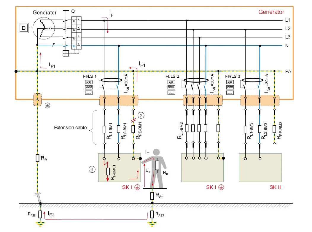
The star point of the generator must be connected to the earthing system. To do this, adjustments usually have to be made on the generator's terminal board.
In order to set up the necessary earthing system, an earth spike must be driven in, and the loop or earthing resistance must be determined by a qualified electrician.
One residual current device (RCD) per socket-outlet is required for the TN and TT systems – even with regard to the fact that the generators are deployed outdoors and are designed for use by untrained, unqualified personnel. Accordingly, DIN VDE 0100-410 (VDE 0100-410):2007-06 section 411.3.3 "Additional protection" must also be complied with.
The proper functioning of the protective measure – protection by shutdown – must be tested by a qualified electrician.
If the generator is operated as an unearthed power supply (IT system), an insulation monitoring device (IMD) conforming to DIN EN 61557-8 (VDE 0413-8):2015-12 that reports a first insulation fault with a visual and/or audible warning must be installed.
If a second insulation fault occurs on another conductor, the system must be shut down accordingly by a circuit breaker. In this case, too, proper functioning must be verified by a qualified electrician. In DIN 6280:1986-10, a loop resistance of max. 1.5 ohms is specified for this.
To summarise, whenever a mobile generator is used as a TN, TT or IT system, an earthing system and a qualified electrician are needed to confirm the proper functioning of the necessary protective and monitoring devices. Of course, this is not feasible in practice and, ultimately, it is associated with costs.
To avoid this, the "protective separation" protective measure is used. But here, too, there are a number of things to consider if it is to be usable by individuals without an electrical engineering background.
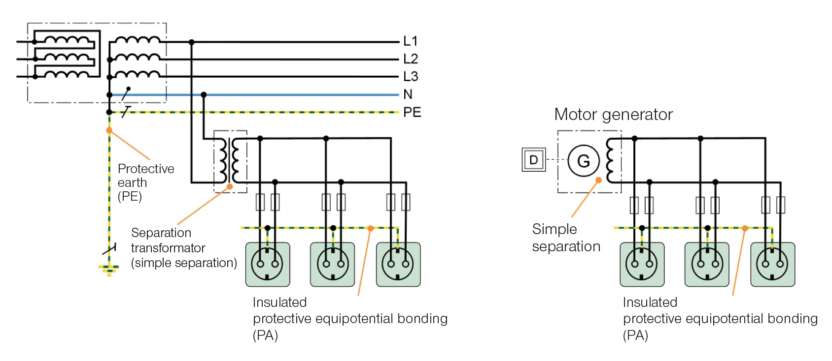
Protective separation is an independent protective measure in which, in accordance with DIN VDE 0100-410 (VDE 0100-410):2007-06 section 413,
from other circuits and earth.
Accordingly, protective separation derives its protective effect from the fact that the secondary circuit is separated galvanically from the mains supply and earth, or, in the case of a mobile generator, the output winding is separated from earth. When an active conductor is touched, the high insulation resistance and low system leakage capacitances (Ze very large) of the secondary circuit to earth means that virtually no current can flow through a human.
However, the size of the system leakage capacitance is negatively affected by the length of the wire and the number of loads or the resulting impedance between the active conductor and earth (Z becomes smaller). For this reason, the instruction to limit this protective measure to the supply of an electrical consumable applies generally, and the length of the wire must also be borne in mind. For fault protection, additional measures are still needed:
Provided they comply strictly with these requirements, protective separation with a load may also be used by individuals without an electrical engineering background. In practice, however, mobile generators are usually equipped with more than one socket-outlet. Therefore, the requirements of Annex C.3 of DIN VDE 0100-410 (VDE 0100-410):2007-06 apply as well.
Annex C.3 of this standard describes the protective measures with more than one consumable, which may only be operated and monitored by qualified electricians or individuals who have received electrical training.
The biggest problem associated with this protective measure is the requirement for the generator assembly to be insulated, which is often difficult to implement in practice because, for example, the metal frame of a generator or the metal housing of a protection class I equipment item, and consequently the protective earth or protective bonding conductor can be connected to the possibly damp soil by unintentional contact.
A discussion of this and the necessary protective measures for mobile generators are described in the new edition of DIN VDE 0100-551 (VDE 0100-551):2017-02 and in Annex ZC thereof.
The use of the protective measure in conjunction with independent power generation facilities is described in section ZC.3.2. If only one equipment item is connected, the requirements of DIN VDE 0100-410 (VDE 0100-410):2007-06 section 413 apply.
If more than one equipment item is connected, the requirements of section ZC.3.2.2 apply. This section initially assumes that the cable length does not exceed 500 m and the product of voltage in volts and total length in metres is not greater than 100,000. This has been specified mainly to address the eventuality that, if a short circuit occurs between the two active conductors, the generator's overcurrent protection must respond appropriately.
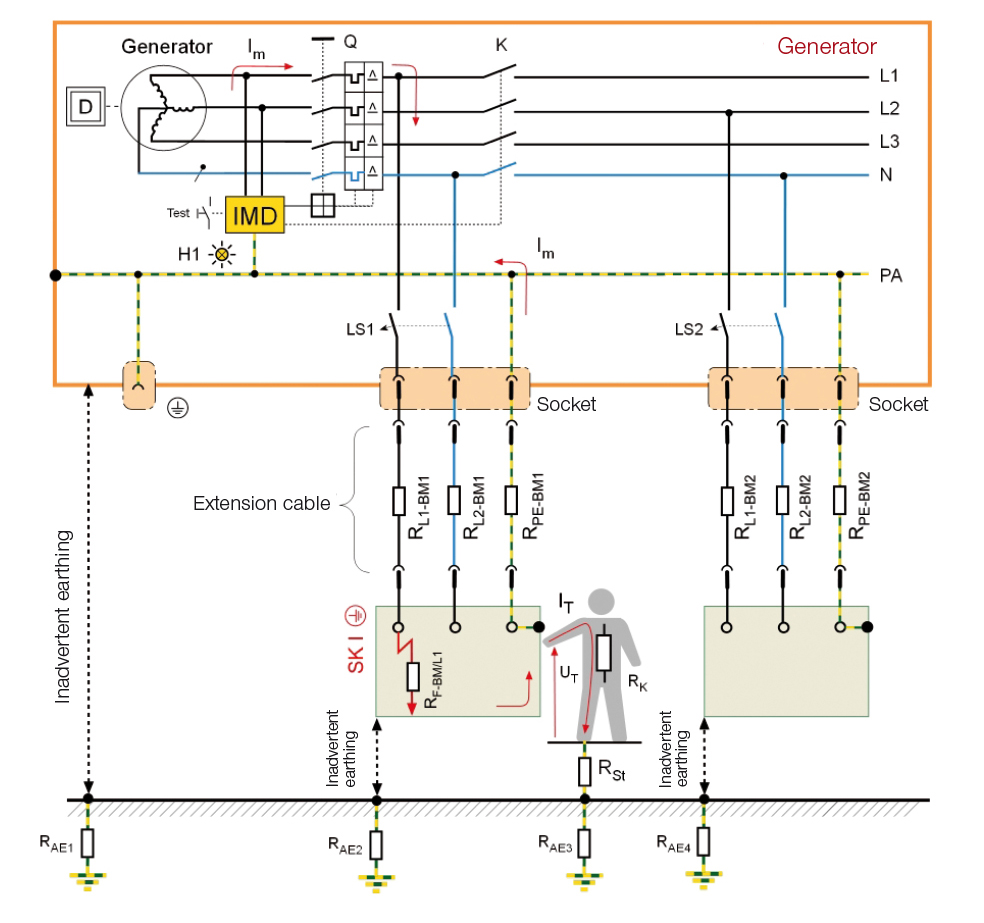
This protective measure is designed so that an insulation monitoring device (IMD) is installed between the active conductors and earth or the equipotential bonding in accordance with DIN EN 61557-8 (VDE 0413-8):2015-12, which monitors the insulation resistance at all times. If this insulation resistance falls below the value of 100 Ω/V of the nominal voltage, the insulation monitoring device shuts down the output circuit of the generator or the electrical load within one second.
Since, in this case, shutdown takes place as soon as a first insulation fault occurs, the network reach does not have to be limited, and rapid shutdown (short circuit/overcurrent protection must remain in effect) is not necessary in the event of second fault. Another advantage associated with the use of an IMD is that, according to DIN EN 61557-2 (VDE 0413-2):2008-02, in the case of periodic verification insulation measurement with a measuring instrument is no longer required. The time-consuming disassembly of a generator's switch cabinet is thus no longer necessary.
When choosing an IMD, it is to be ensured that the measuring technique is suitable for this application. Simple devices with superimposed measuring voltage are usually not able to detect insulation faults with DC components or higher system leakage capacitances.
Until now, it has always been the case that a generator with more than one equipment component must not be used except by a qualified electrician or a person who has received appropriate electrical training. The new DIN VDE 0100-551 (VDE 0100-551):2017-02 now allows the generator to be switched on in the absence of a qualified electrician, provided the following requirements are fulfilled:
If the mains power supply fails, this can have significant negative effects if a permanent emergency power supply has not been installed. Examples of these are agricultural operations and fire stations. In section ZC.3.4, a power generation device is presented in which the operating mode of the generator can be changed using an all-pole selector switch. Operating mode 1 corresponds to a generator with protective separation, insulation monitoring and shutdown.
Operating mode 2 is for feeding into the permanently installed electrical system, e.g. an agricultural business facility. An RCD has to be installed in the feed circuit for this purpose. According to 705.411.1 of DIN VDE 0100-705 (VDE 0100-705):2007-10, the rated residual current must not exceed 300 mA. Since the PEN conductor is not permitted, the cable from the generator to the mains supply socket must be designed as a five-core cable.
If power is to be fed to a system while it is switched off in operating mode 2, this is only possible if a permanently installed feed circuit with corresponding plug connector is present in the building. The feed-in is then assured via a CEE plug and corresponding cable, wherein the socket must have a protective earth contact at the one o' clock position to prevent it from being mistaken for other connecting cables and conductors.
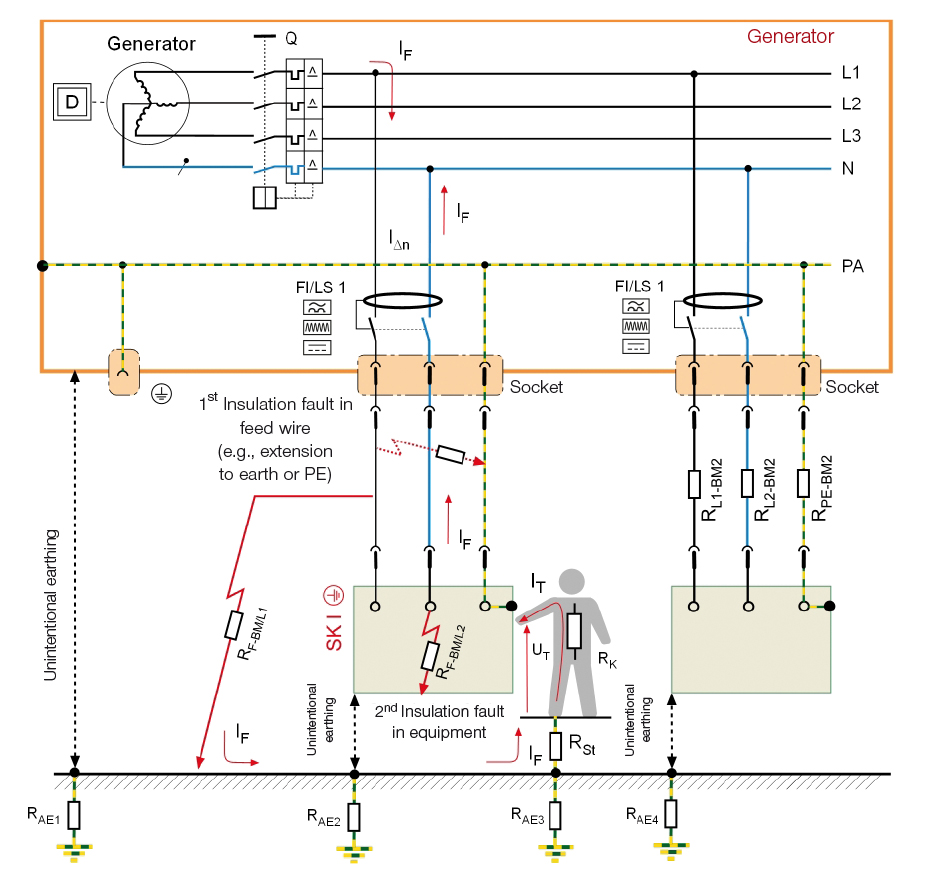
The second option for protection against electric shock is the use of residual current devices (RCDs). In this case, however, it should be noted that a dedicated RCD must be provided for each socket, since a first fault cannot be detected with just one RCD. When choosing the RCD it must be borne in mind that only type B RCDs must be used.
Type A RCDs must only be used if it has been ensured that no DC residual currents > 6 mA can occur. However, this is not possible particularly in the case of three-phase equipment with electronic components or speed-regulated drives. DC residual currents can interfere with the tripping behaviour of type A RCDs – in terms of both response time and response behaviour.
In extreme cases, a DC residual current can even prevent the type A RCD from tripping. A type B RCD is absolutely essential, precisely with generators for which it cannot be stated with certainty that frequency-regulated equipment items will not be connected.
Another aspect to be considered is that the measurement technology of RCDs means that they are unable to detect symmetrical insulation faults (one insulation fault from each active conductor to the equipotential bonding or earth – uniformly moistened plug). A RCD is not actuated in this case either, as is shown in Fig. 4.
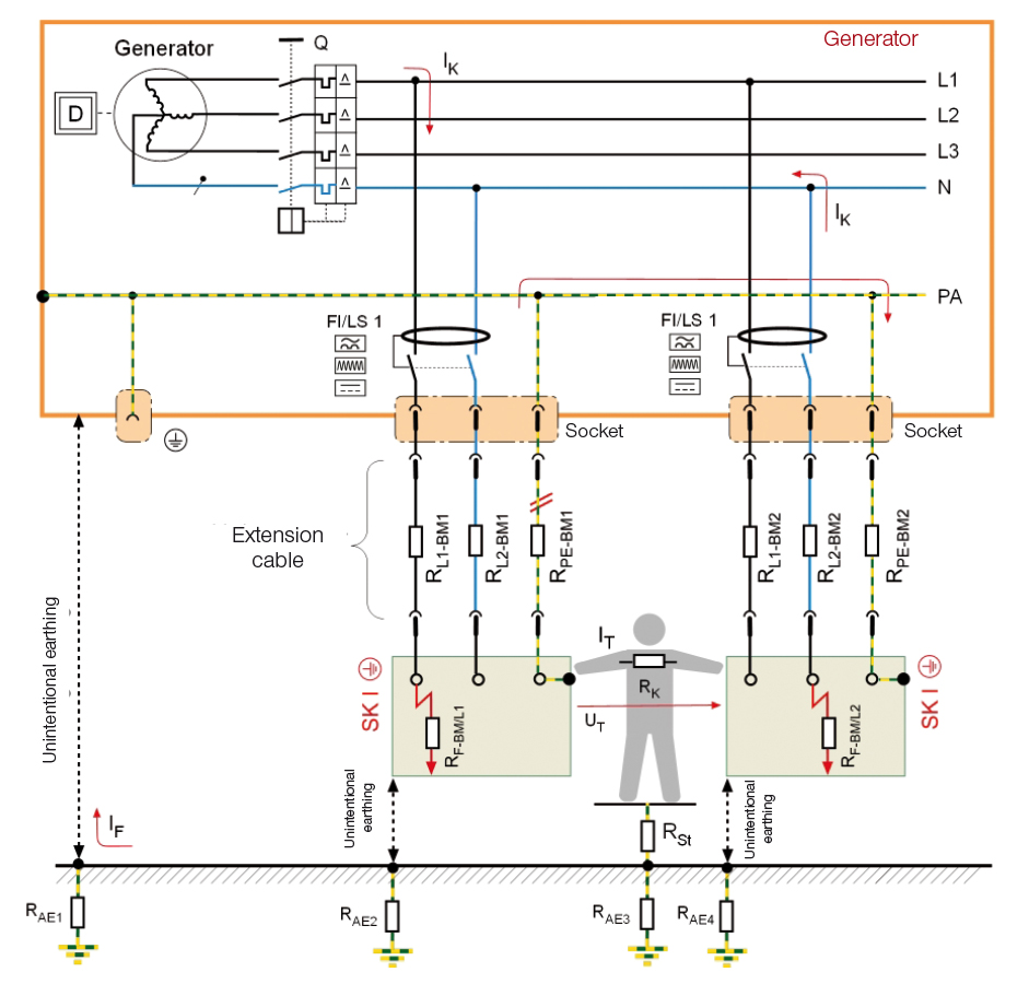
A practical example is an insulation fault in the protected system part (e.g. exposed wire in the secondary circuit touches damp ground), i.e. a fault to frame between a connecting wire and the conductive surrounding of the installation neutralises the protective effect of the protective separation.
This is true even when the metal frame of a generator is earthed via the environment, e.g. by damp ground or water. In such cases, dangerous contact voltages are the direct consequence if the protected device randomly has a second fault (fault to frame) with another external conductor (Fig. 5).
In these cases, the full operating voltage of the isolating transformer is effective as the contact voltage (second fault). This can only be remedied with an insulation monitoring device (IMD) or a combination of several different protective measures.
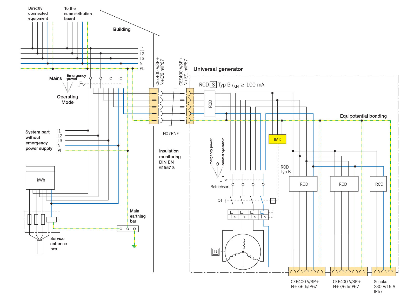
To ensure that the protective effect of the protective separation is not disabled, particular care must be taken so that an insulation fault does not occur in the cables and wires on the protection-separated side (secondary circuits) of the system.
In view of the risk of cable damage, it is recommended to limit the (total) conductor length to 500 m and to ensure that the product of the nominal voltage in volts and the conductor length in metres does not exceed a value of 100,000. Flexible cables must satisfy at least design specification H07RN-F.
Another question to be considered with this protective measure is that in the case of 3ph+N generators a first insulation fault causes a voltage shift: The result of this is that the single-phase equipment items which are not connected to the phases affected by the insulation fault are exposed to a higher voltage between the active conductor and earth. This may possibly damage the equipment (particularly suppression capacitors).
Provided a small number of requirements such as
are carefully observed, the protective measure protective separation with insulation monitoring and disconnection represents an effective measure for ensuring protection against electric shock, and also has the advantage that it can be installed immediately if necessary, even without a qualified electrician.
Dipl.-Ing. Harald Sellner, S-N Dipl.-Ing. Holger Potdevin, S-N
References:
Standards are available for purchase at www.vde-verlag.de or www.beuth.de
Products
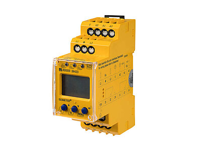
Insulation monitoring device for mobile generators

Insulation monitoring device for mobile generators