
Compared to TN systems or TT systems ("earthed systems"), the IT system ("unearthed system") is a system type that is rarely used, even though in many cases it would be the better alternative.
Why do we then settle for worse alternatives in practice?
The answer appears to be the following: habit, convenience, ignorance. The IT system is not very well known in the field. In fact, this topic is barely touched upon in universities and during apprenticeships. As a result, the earthed system has been established as standard and continues to spread.
The IT system is rarely used and when it is, it is mostly in applications where its advantages cannot be waived. This is the case in, for instance, operating theatres and intensive care units or in railway signalling technology. Why? Because here, human lives are at stake. But isn't it always about human lives in power supply systems?
The main difference between the IT system and the TN or TT system is a conductive connection between the star point of the transformer which supplies the system and earth. This connection exists in the earthed system, but not in the unearthed system.
What is the big difference regarding the impact if there is only such a small difference in the implementation? If a person touches a live conductive enclosure in an intact unearthed system, what happens is: generally NOTHING! Why? Because a current does flow but it is very small since it depends on leakage capacitances and the enclosure is earthed.
What is this like in an earthed system? Here, we set up a closed circuit in advance and then, to a certain degree, just wait for the fault. If in this case a person touches a live conductive enclosure, without an overcurrent protective device a fault current would immediately flow through the person due to the low-resistance connection to the supply transformer. To ensure that the required protective measures function at this moment, it must be tested at regular intervals.
But how often are these tests actually carried out?
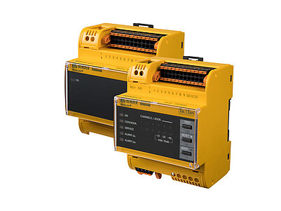
Insulation faults can be located during operation or in de-energised condition via so-called insulation fault location systems (IFLS).
For this purpose, devices for stationary installation and mobile devices are available. In principle, fault location is also possible in earthed systems using residual current monitoring (RCM) technology. However, with the restriction that this technology only works in energised systems and, unlike IT systems, remains restricted to asymmetrical insulation faults.
If an insulation fault or even a dead earth fault occurs in an unearthed system, shutdown is not necessary.
This is also the reason why IT systems are mandatory, e.g. in intensive care units. In the event of an insulation fault, the supply to life-supporting equipment is maintained. The IT system is in general perfectly suitable for all applications in which shutdowns are unwanted, would have serious consequences or would cause high costs – in the process industry, in data centres, in automation, basically everywhere.
Control circuits of all types are of particular importance. Controller errors and failures in control circuits – e.g. in a substation or in a nuclear power plant – can have serious consequences. Based on the information provided by the insulation monitoring device it is possible to plan long-term servicing and maintenance work in the IT system and avoid unplanned service calls to rectify malfunctions.
Another crucial advantage is that deteriorations of the insulation level can be detected immediately.
In an earthed system, fault currents can be resolved in the single-digit milliamp range by means of sophisticated residual current monitoring (RCM) technology – but no further. Even if it were possible to select only the ohmic portion of the residual current, this would imply detection of the deterioration of the insulation level below 40 kΩ at a mains voltage of 400 V and a resolution of 10 mA.
This is a significant improvement compared to an earthed system not being monitored that unexpectedly shuts down. In an IT system, an insulation value of 40 kΩ corresponds to the recommended main response value. It is even possible to measure in the megaohm range and above – which implies a factor of at least 1,000 compared to the earthed system. Therefore, insulation deteriorations in an unearthed system can be measured and rectified much earlier.
In an IT system, symmetrical faults can be detected via an active measuring insulation monitoring device. Symmetrical faults are insulation deteriorations of a similar magnitude on all line conductors.
Such faults are quite common. For example, the insulation values in photovoltaic systems often deteriorate to a similar degree on the positive and the negative side.
RCDs for pure DC systems, such as battery systems, are currently not available. Instead either residual current monitors (RCM) with a DC supply voltage can be used or an IT system with insulation monitoring can be implemented.
In DC systems the ISOMETER® iso685 also offers the advantage that it indicates whether the fault is on the positive or negative side.
DC fault currents may occur if there are battery systems, converters, switched-mode power supplies etc. in the AC system.
The widespread type A RCDs for pure AC systems are not suitable in this case. In the earthed system, it is only possible to use type B RCDs or it must be ensured by other means (RCM technology) that the system is shut down in the event of DC currents above 6 mA.
A reasonable alternative is to operate the installation as an unearthed system and monitor it using an insulation monitoring device.
Since an insulation monitoring device is an active measuring device, it can also monitor de-energised IT or TN systems. This aspect is important, for example, for rail switch points heating unit, fire pumps on ships, redundant cooling systems in nuclear power plants. That way, it is also possible to detect an insulation fault in a rail switch points heating unit in summer so it can be repaired in time. Otherwise, the fault would only be detected once the installation is switched on in winter – in the form of immediate failure of the installation exactly when it is needed.
The insulation monitoring device stipulated for IT systems continuously monitors the insulation value.
In contrast, during the periodic tests (keyword periodic verification) only the instantaneous state of the insulation is measured. This state can deteriorate dramatically immediately after the test and remain unnoticed for a long time.
Continuous monitoring by means of the additional usage of residual
current monitoring systems (RCM technology) is also possible in earthed systems.
Insulation faults in electrical installations are the most common cause of fire. In an IT system, the risk of fire is very low.
Firstly, insulation faults can be detected and rectified at an early stage in their evolution. Secondly, as there is no low-resistance return path, a current large enough to cause a fire does not flow in the event of an insulation fault. The restriction to systems that do not have an excessively system leakage capacitance also applies here.
The ISOMETER®s iso685 and iso1685 are capable of continuously recording system parameters with date and time assignment over many years.
In conjunction with other recorded system information, this aspect allows event-based fault analysis and makes it easier to find and rectify faults that occur sporadically; it also improves the information available for making decisions on future investments. The evaluation can be undertaken in the device itself or via Ethernet.
Nowadays, systems contain less and less (ohmic) loads. The light bulb has been replaced by energy-saving bulbs or LEDs, computers and television are connected to the mains via switched-mode power supplies, the washing machine contains a frequency converter and a high number of frequency converters are used for industrial motors.
A powerful insulation monitoring device in the IT system has no problem with these issues and measures the insulation value for the entire system correctly. The IT system is particularly suitable for usage with converters, since even in the event of a dead insulation fault in the link circuit of large converter drives in an IT system due to DC currents and the related saturation effects in iron cores, the inductive elements or supplying generators and transformers cannot be destroyed.
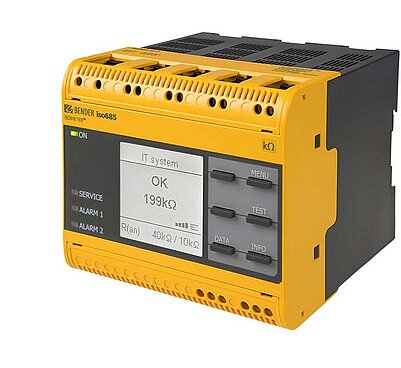
The ISOMETER® iso685 was developed for monitoring systems with frequency converters and makes it possible to logically link system parameters to shut down drives automatically in a critical system state. Differentiation between faults in the link circuit and on the motor side in converter drives is possible in the iso685 without additional expense or other equipment.
Stray currents often cause problems in earthed systems. These are the currents that do not flow via the L, N and PE conductors, but search for other paths.
They cause corrosion and pitting on pipes, lightning protection systems, ball bearings, foundation earths and other conductive components. They can also result in the destruction of screens on signal cables and even fire; as a consequence magnetic field interference can occur that causes problems in IT and communication systems. As the return path to the transformer's star point is not closed in the unearthed system, stray currents cannot propagate in unearthed systems.
IEC 62109-1:2010 describes the possibility of reducing the overvoltage category from CAT IV to CAT III by means of an isolating transformer, an optocoupler or similar galvanic separation, since the currents resulting from transients are not as high as those caused by earthed systems.
The practical consequence is that components in the electrical loads in the IT system are subject to less voltage spikes and as result have a longer service life.
Very large IT systems can become too complex and contain an inadvertently high system leakage capacitance. It is therefore recommended to split very large IT systems into separate units by means of isolation transformers. The additional costs and performance losses that this may cause are negligible.
The division into galvanically isolated subsystems also has advantages, such as the filtering effect in relation to interference or the possibility to specifically adjust the voltages to the loads supplied. What constitutes a large system must be evaluated in the specific case and depends on the system parameters. For instance, the world's largest PV fields can be monitored entirely by individual ISOMETER®s of type isoPV. This means that a single ISOMETER® does not miss a faulty connector, a damaged cable or a damaged PV module, despite an installation the size of ten football pitches or more.
In an IT system with an insulation fault on one conductor, the line-to-line voltages of the other conductors to the earth potential increase.
In the event of a dead earth fault on a conductor in the 230 V system, the voltages of the other conductors increase in relation to the earth potential to approx. 400 V. System components on which the potential in relation to earth is an issue, in particular Y capacitors and overvoltage limiters, should therefore be suitable for the maximum rated voltage. Voltage increase can be avoided when the secondary side of the transformer is connected in Delta mode.
The IT system has many advantages over earthed systems and is not only suitable for the high demands in operating theatres or nuclear power plants but for practically every application. At present, in many cases the IT system is not even considered, even if it would be a better choice.
The latest generation of insulation monitoring devices offers numerous economical and technical advantages that benefit the operator. Sometimes, the costs of an insulation monitoring device are used as an argument against an IT system. Yet, the opposite is the case: Considering the advantages mentioned above and the related economical effects, from a commercial point of view using an IT system always pays off!
| Name | Category | Size | Language | Timestamp | D-/B-Number |
|---|---|---|---|---|---|
| Product Overview ISOMETER®/ISOSCAN® | Product Overviews | 5.3 MB | EN | 2024/02/1616.02.2024 | |
| Why the IT System is Often the Best Choice for Power Supply Systems of All Types | Technical article | 3.0 MB | EN | 2019/07/1111.07.2019 | |
| Initial and Periodic Verification of IT Systems | Technical article | 621.5 KB | EN | 2020/03/0202.03.2020 | |
| High Availability for Reliable Operation in Waste Water Treatment Facilities | Technical article | 601.8 KB | EN | 2019/05/1313.05.2019 | |
| IT System Ensures Electrical Safety at the Munich Airport | Technical article | 284.0 KB | EN | 2019/05/1313.05.2019 | |
| The Stone Age Meets Modern Network Protection Technology | Technical article | 338.5 KB | EN | 2019/05/1313.05.2019 | |
| The Largest Photovoltaic System in Latin America | Technical article | 447.8 KB | EN | 2019/05/1313.05.2019 |
Products

Insulation monitoring device for inverter applications and large industrial plants

Insulation fault locator for localisation of insulation faults in main circuits

Insulation monitoring device for inverter applications and large industrial plants

Insulation fault locator for localisation of insulation faults in main circuits